BE/HR-E-IIB1
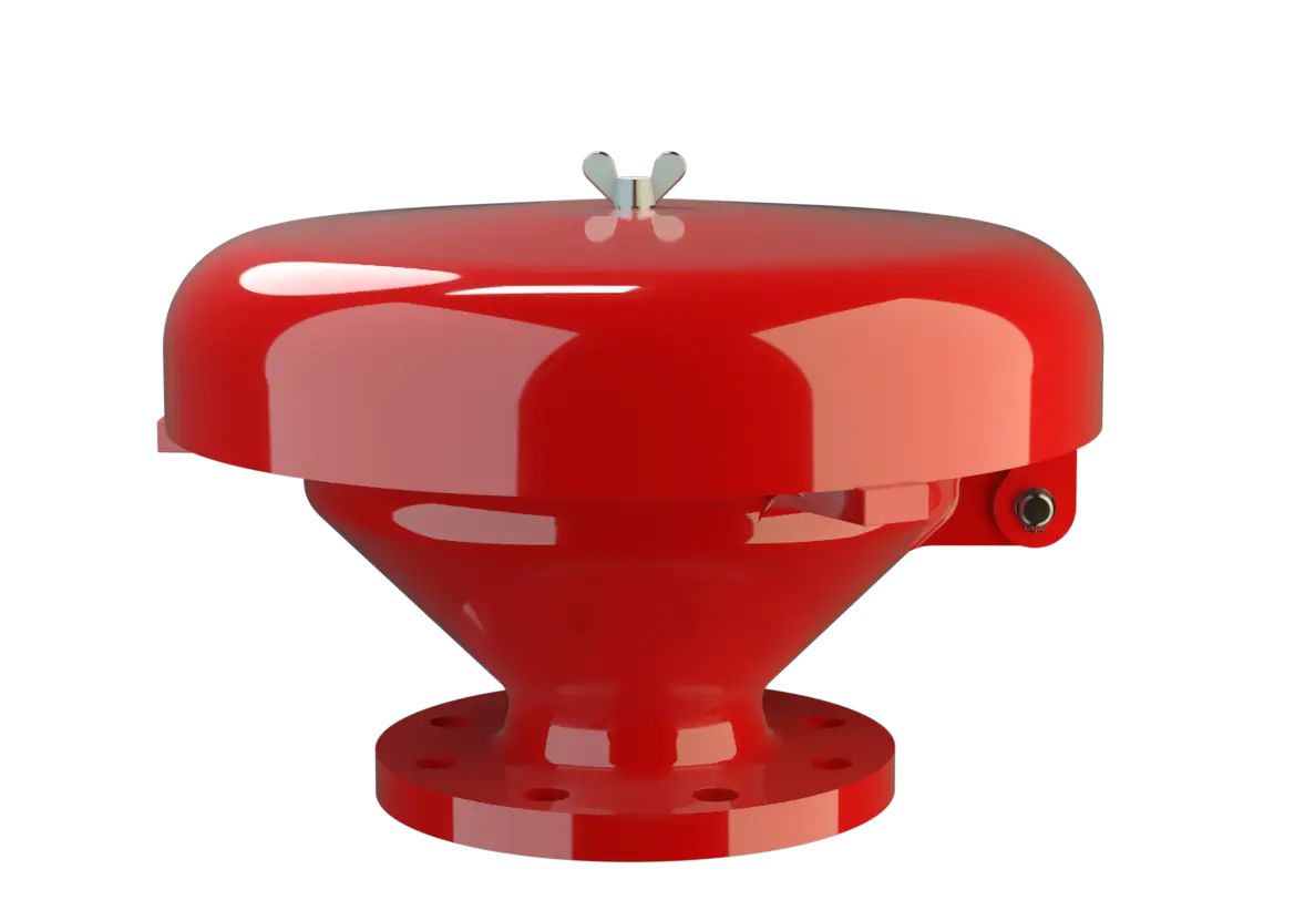
Deflagration Flame Arrester, endurance burning proof, End-of-Line
Caractéristiques
Fonction et description
Protection Against Atmospheric Deflagration and Endurance Burning
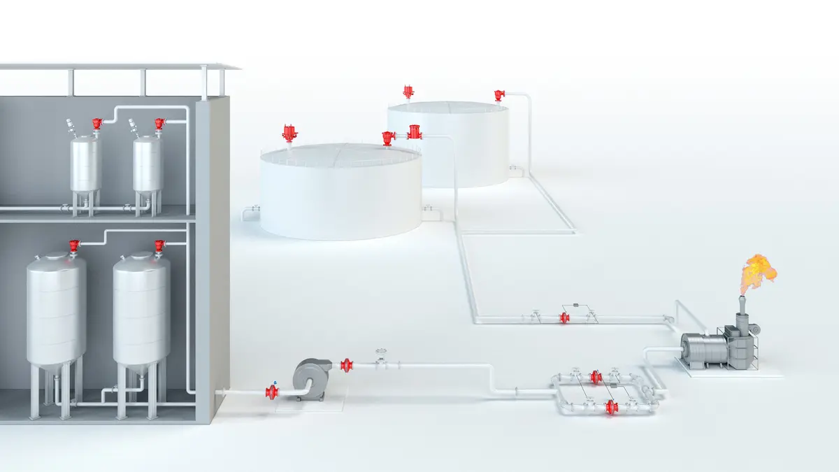
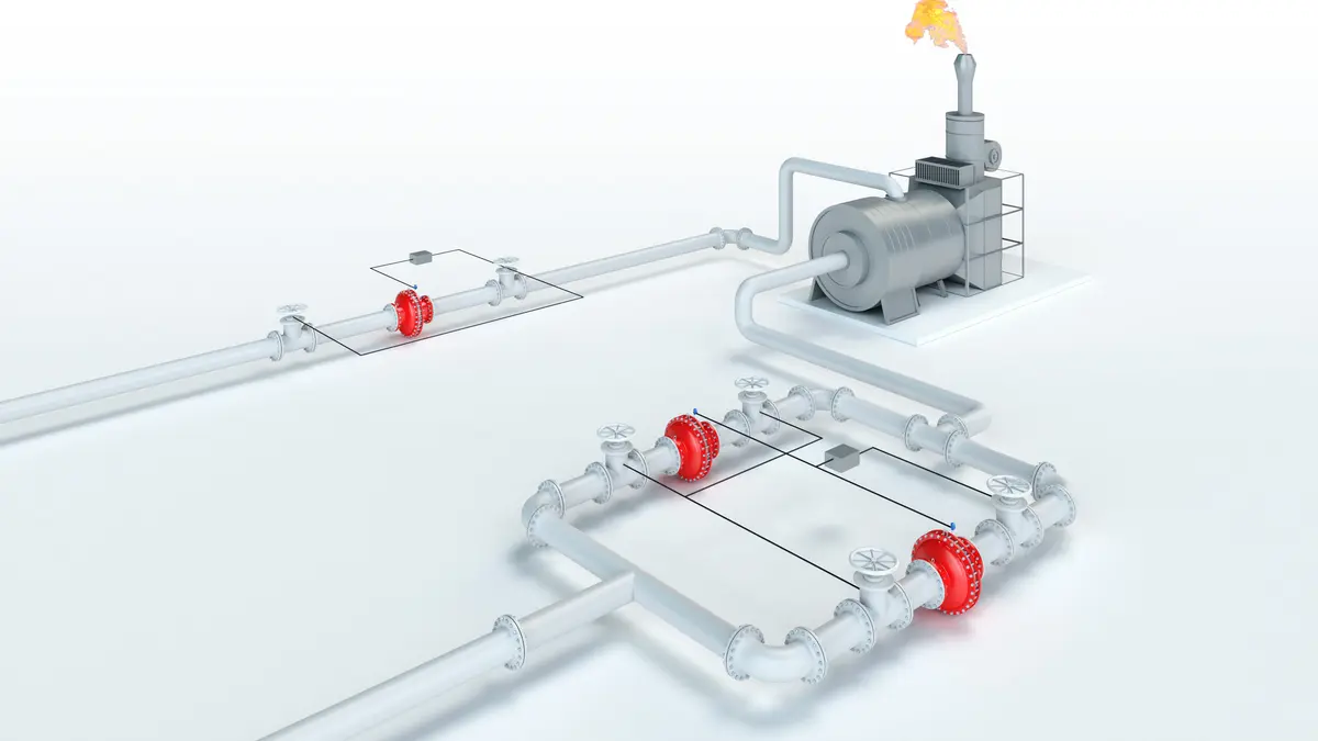
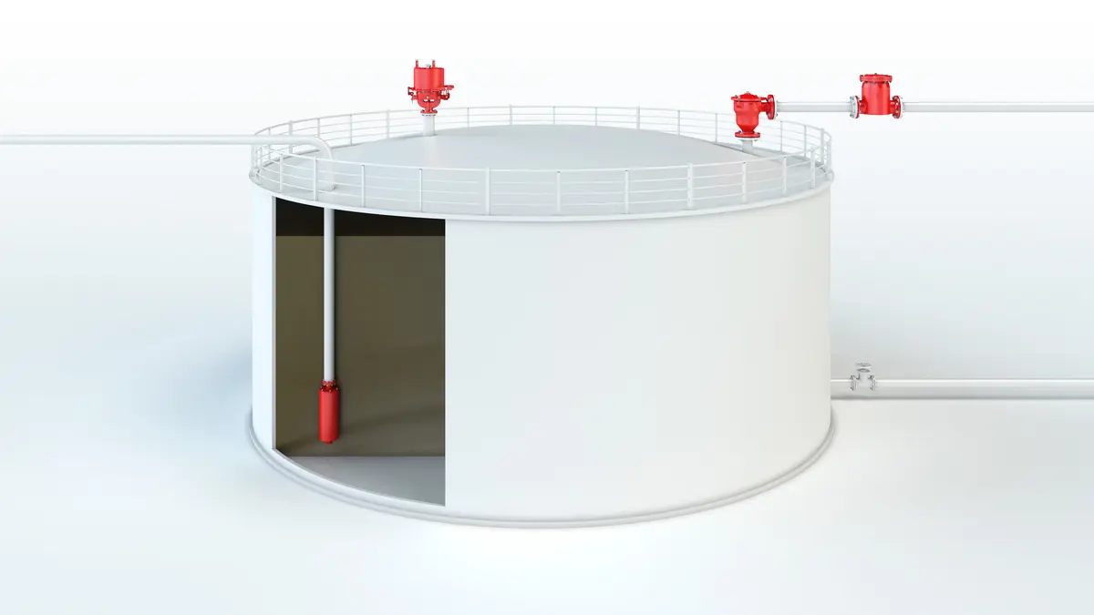
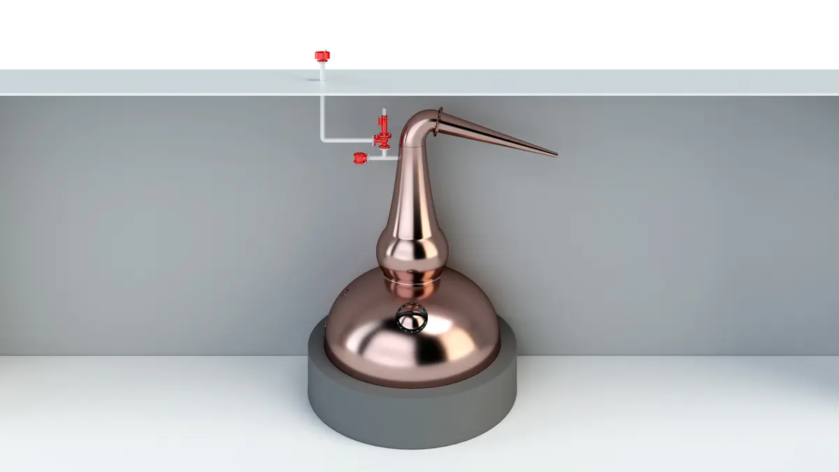
The PROTEGO® BE/HR-E End-of-Line Deflagration Flame Arrester was specifically developed for vessels which are not pressurized and store Ethanol or other alcohols with a MESG ≥ 0,85 mm. The combustion of alcohol requires a modified Flame Arrester Element design to provide protection against endurance burning. In addition, the device provides protection against atmospheric deflagration. It is typically installed on in-breathing and out-breathing vent lines to prevent flame transmission into the vessel or plant caused by endurance burning or atmospheric deflagration.
Main Component – PROTEGO® Flame Arrester Unit
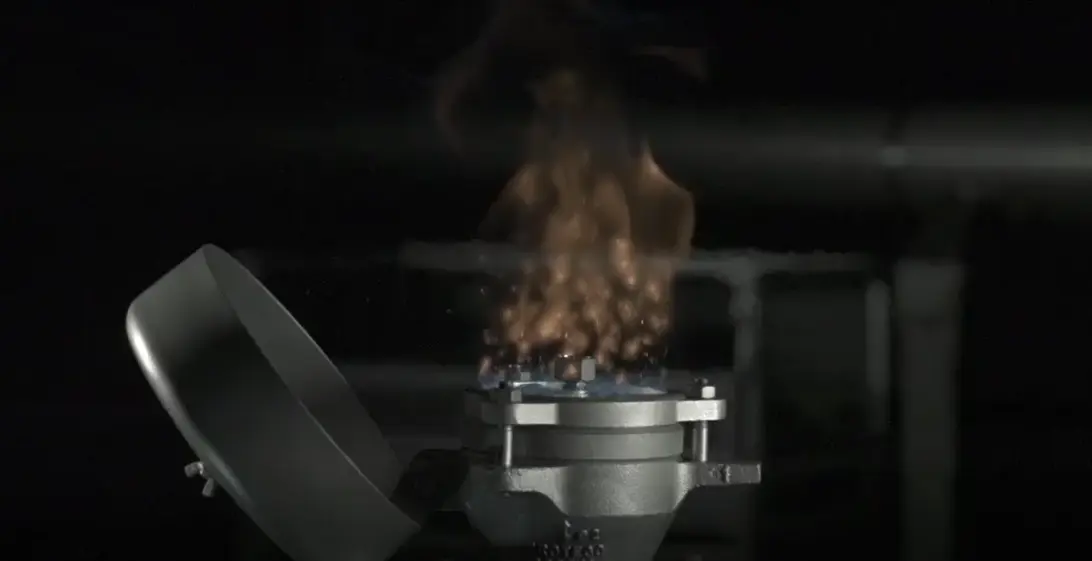
The PROTEGO® BE/HR-E consists of the housing (1), a weather hood (2), and the PROTEGO® Flame Arrester Unit (3). During normal operation, the metal weather hood is in a closed position. If a flame burns on the Flame Arrester Element surface, the melting element (5), located in a center position, will melt, and the spring-loaded weather hood will open. The PROTEGO® Flame Arrester Unit consists of two FLAMEFILTER® discs (4) which are installed in a FLAMEFILTER® casing.

For Explosion Group IIB1
The PROTEGO® BE/HR-E End-of-Line Deflagration Flame Arrester is available for alcohols and other substances with a MESG ≥ 0,85 mm. The standard design can be used for operating temperatures up to +60°C / 140°F. EU conformity according to the currently valid ATEX directive. Approvals according to other national/international regulations on request.
Dimensions
To select the nominal size (DN), please use the flow capacity charts on the following pages
| DN | 80 / 3" | 100 / 4" |
| a | 353 / 13.90 | 353 / 13.90 |
| b | 250 / 9.84 | 250 / 9.84 |
Dimensions in mm / inches
Dimensions for Deflagration flame arrester with heating jacket upon request
Material selection for housing
| Design | B | C |
| Housing | Steel | Stainless Steel |
| Weather Hood | Steel | Stainless Steel |
| Flame arrester unit | A | A, B |
Special materials upon request
Material combinations of flame arrester unit
| Design | A | B |
| FLAMEFILTER® cage | Stainless Steel | Stainless Steel |
| FLAMEFILTER® | Stainless Steel | Hastelloy |
| Spacer | Stainless Steel | Hatelloy |
Special materials upon request
Selection of explosion group
| MESG | Expl. Gr. (IEC / CEN) | Gas Group (NEC) |
| ≥ 0,85 mm | IIB1 | – |
Special approvals upon request
Flange connection type
| EN 1092-1; Form B1 |
| ASME B16.5 CL 150 R.F. |
other connections upon request
Design Types and Specifications
There are two different designs:Special designs available on request
Flow Capacity Chart
The flow capacity charts have been determined with a calibrated and TÜV certified flow capacity test rig. Volume flow V in (m³/h) and CFH refer to the standard reference conditions of air ISO 6358 (20°C, 1bar). For conversion to other densities and temperatures refer to Sec. 1: “Technical Fundamentals”.