DR/SV
In-Line Detonation Flame Arrester with shut-off valve, for stable detonations and deflagrations in a straight through design, unidirectional
Caractéristiques
Fonction et description
Detonation Arrester With the Advantages of a Shut-Off Valve
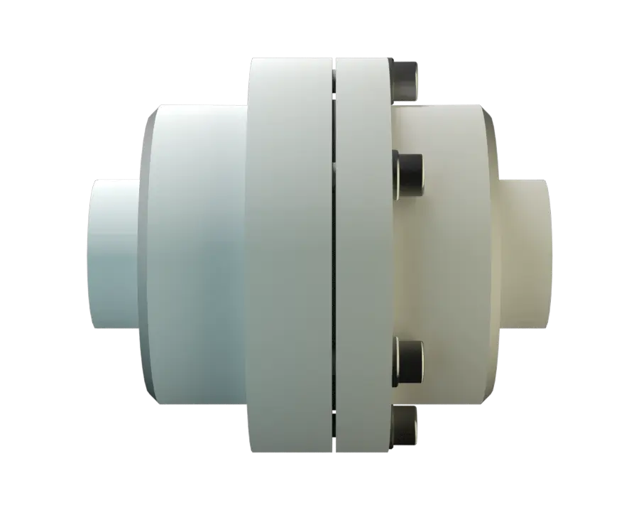
The PROTEGO® DR/SV Flame Arrester Series ideally combines the function of a detonation arrester with the advantages of a Shut-Off Valve. In case of ignition, the fire can be stabilized within the Flame Arrester when the flammable gas continues to flow. Inside the detonation arrester, is a valve (1) that closes in case of fire, stops the additional supply of fuel and extinguishes the flames.
Suction-Side Protection for Compressors and Pumps
Temperature sensors in combination with an emergency switch off do not have to be installed if the type PROTEGO® DR/SV device is used. This device is particularly useful for the sucction-side protection of compressors and pumps.

For Explosion Group IIA
Once a detonation enters the Flame Arrester, energy is absorbed from the detonation shock wave by the central plate disc (2) before the flame is extinguished in the narrow gaps of the two FLAMEFILTER® discs (3). This device can be used for fluids of explosion group IIA (NEC group D). The In-Line Detonation Detonation Explosion, die sich mit Überschallgeschwindigkeit fortpflanzt, gekennzeichnet durch eine Stoßwelle. Flame Arresters are unidirectional and equipped with a threaded connection. The thread can be executed to international standards. The standard design can be used up to an operating temperature of +60°C / 140°F and an (absolute) operating pressure up to 1.1 bar / 15,9 psi. EU conformity according to the currently valid ATEX directive. Approvals according to other national/international regulations on request.
Dimensions
To select the nominal size (DN), please use the flow capacity chart on the following page
| DN | G ½" | G ¾" |
| a | 115 / 4.53 | 115 / 4.53 |
| b | 100 / 3.94 | 100 / 3.94 |
Dimensions in mm / inches
Material selection for housing
| Design | A | B |
| Housing | Brass | Stainless Steel |
| Gasket | WS 3822 | WS 3822 |
| Flame arrester unit | A | A, B |
Special materials upon request
Material combinations of flame arrester unit
| Design | A | B |
| FLAMEFILTER®* | Stainless Steel | Stainless Steel |
| Spacer | Stainless Steel | Stainless Steel |
| Support for FLAMEFILTER® | Brass | Stainless Steel |
| Washer | Brass | Stainless Steel |
* the FLAMEFILTER® are also available in the materials Tantalum, Inconel, Copper, etc. when the listed housing and cage materials are used.
Special materials upon request
Selection of explosion group
| MESG | Expl. Gr. (IEC / CEN) | Gas Group (NEC) |
| > 0,90 mm | IIA | D |
Special approvals upon request
Selection of max. operating pressure
| DN | G ½" | G ¾" |
| Pmax | 1,1 / 15.9 | 1,1 / 15.9 |
Pmax = Maximum allowable operating pressure in bar / psi absolut, higher operating pressure upon request
Specification of max. operating temperature
| ≤ 60°C / 140°F | Tmaximum allowable operating temperature in °C |
| - | Designation |
higher operating temperatures upon request
Type of connection
| Pipe thread DIN ISO 228-1 | DIN |
other types of thread upon request
Flow Capacity Chart
The flow capacity charts have been determined with a calibrated and TÜV certified flow capacity test rig. Volume flow V in (m³/h) and CFH refer to the standard reference conditions of air ISO 6358 (20°C, 1bar). For conversion to other densities and temperatures refer to Sec. 1: “Technical Fundamentals”.