DA-G
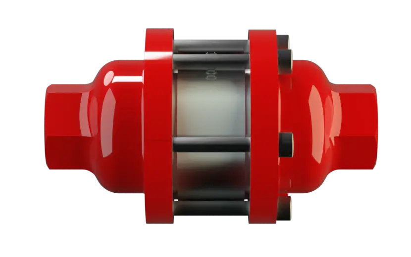
In-Line Detonation Flame Arrester for stable detonations and deflagrations in a straight through design, bidirectional
Características
Función y descripción
For Industrial Use in Gas Analysis Lines
The PROTEGO® DA-G Series is a compact in-line detonation flame arrester for installation in pipes with diameters up to 3“ and is used, for example, in industrial applications such as gas analysis lines. Once a detonation enters the Flame Arrester, energy is absorbed from the shock wave, and the flame is extinguished in the narrow gaps of the FLAMEFILTER® (1).
Main Component – PROTEGO® Flame Arrester Unit
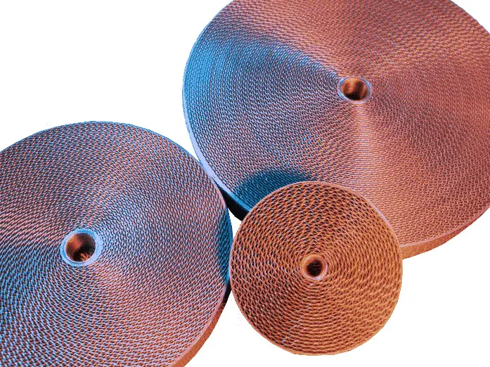
The PROTEGO® Flame Arrester Unit consists of several FLAMEFILTER® discs firmly held in a housing. The gap size and number of FLAMEFILTER® discs are determined by the operating data and parameters of the mixture flowing in the line (explosion group, pressure, temperature). To provide an optimum result between the housing size, number of FLAMEFILTER® discs and their gap size, a device was developed that can be used for all explosion groups - IIA, IIB3 and IIC (NEC Group D, C MESG ≥ 0.65 mm and B). The standard design can be used with an operating temperature of up to +60°C / 140°F and an absolute operating pressure up to 1.1 bar / 15.9 psi. Devices with special approvals for higher pressures (see table 3) and higher temperatures are available upon request.

Many Individual Certifications
The device is bi-directional and equipped with a threaded connection. This can be adapted to international standards. The detonation arrester can be used at any location in the pipe, regardless of the location of the ignition source. EU conformity according to the currently valid ATEX directive. Approvals according to other national/international regulations on request.
Dimensiones
To select the nominal size (DN), please use the flow capacity charts on the following pages
| DN | G ½" | G ¾" | G 1" | G 1¼" | G 1½" | G 2" |
| a | 80 / 3.15 | 80 / 3.15 | 100 / 3.94 | 100 / 3.94 | 155 / 6.10 | 155 / 6.10 |
| b | 55 / 2.17 | 55 / 2.17 | 76 / 2.99 | 76 / 2.99 | 124 / 4.88 | 124 / 4.88 |
| c (IIA) | 112 / 4.41 | 112 / 4.41 | 122 / 4.80 | 122 / 4.80 | 205 / 8.07 | 205 / 8.07 |
| c (IIB3 and IIC) | 135 / 5.31 | 135 / 5.31 | 145 / 5.71 | 145 / 5.71 | 205 / 8.07 | 205 / 8.07 |
| d | — | — | — | — | 400 / 15.75 | 400 / 15.75 |
| SW | 32 / 1.26 | 32 / 1.26 | 50 / 1.97 | 50 / 1.97 | 75 / 2.95 | 75 / 2.95 |
Dimensions in mm / inches, SW= width across flats
Selección de materiales para la vivienda
| Design | B | C |
| Housing | Stainless Steel | Hastelloy |
| Gasket | PTFE | PTFE |
| FLAMEFILTER®* | Stainless Steel | Hastelloy |
* the FLAMEFILTER® are also available in the materials Tantalum, Inconel, Copper, etc. when the listed housing and cage materials are used.
Special materials upon request
Selección del grupo de explosión
| MESG | Expl. Gr. (IEC / CEN) | Gas Group (NEC) |
| > 0,90 mm | IIA | D |
| ≥ 0,65 mm | IIB3 | C |
| < 0,50 mm | IIC | B |
Special approvals upon request
Selección de la máxima presión de operación
| Expl. Gr. | DN | G ½" | G ¾" | G 1" | G 1¼" | G 1½" | G 2'' |
| IIA | Pmax | 1,2 / 17.4 | 1,2 / 17.4 | 1,1 / 15.9 | 1,1 / 15.9 | 1,1 / 15.9 | 1,1 / 15.9 |
| IIB3 | Pmax | 1,1 / 15.9 | 1,1 / 15.9 | 1,1 / 15.9 | 1,1 / 15.9 | 1,4 / 20.3 | 1,4 / 20.3 |
| IIC | Pmax | 1,1 / 15.9 | 1,1 / 15.9 | 1,1 / 15.9 | 1,1 / 15.9 | 1,6 / 23.2 | 1,6 / 23.2 |
Pmax = maximum allowable operating pressure in bar / psi absolute, higher operating pressure upon request
Especificación de la máx. temperatura de operación
| ≤ 60°C / 140°F | Tmaximum allowable operating temperature in °C |
| - | Designation |
higher operating temperatures upon request
Tipo de conexión
| Pipe thread DIN ISO 228-1 | DIN |
other types of thread upon request
Modelo y especificación
There are three different designs available:*Resistance thermometer for device group II, category (1) 2 (GII cat. (1) 2)
Flange connection available upon request
Diagrama de flujo volumétrico
Los diagramas de flujo volumétrico han sido determinados con un banco de pruebas de caudal calibrado y certifi - cado por TÜV. El flujo volumétrico V. en [m³/h] y el CFH se refi eren a las condiciones estándar de referencia de aire según ISO 6358 (20°C, 1bar). La conversión a otras densidades y temperaturas están referidas en el Vol. 1: “Fundamentos Técnicos”.